The following test rig was built to apply a residual strength load to an out-of-service F18 outer wing. My part in this was just the design of the test rig, so that is the bit I’ll describe. Others did the smart work of working out suitable load cases and analysis of test results.
You may have seen light aircraft wings being tested by loading them with bags of weights. The wing is usually mounted upside down and piles of weights are stacked on the wing in a way to represent air loads at Design Limit Load (DLL) or Design Ultimate Load (DUL). DLL is the maximum load that the aircraft should ever see in service, but hopefully very rarely. DUL is usually 1.5 times DLL and is the maximum load that the aircraft should be able to survive, although not necessarily without sustaining permanent damage, which roughly means that it can bend but not break. In this case, it wasn’t practical to load the wing with weights. Military aircraft are much stronger heavier structures than light aircraft and the pile of weights would have been enormous, but we also wanted to apply a variety of load cases because different manoeuvres load the wing in different ways.
The part of the wing we were interested in, the outer wing, is only about 2 metres long, just the bit that can be folded. It is an immensely strong structure made of 7050 aluminium and titanium with carbon fibre composite skins. The wing fold mechanism is actually a series of electrically driven planetary gearboxes with lugs out each side to connect the inner and outer section of the wing. The leading edge of the wing is also attached by planetary gearboxes so that it can be drooped for lower flight speeds. There is a huge hydraulically driven aileron and the wingtip carries a missile launch rail, so you can see there is a fair bit of machinery in a small space.
As is the case for many tests, we started the rig design process without all the information we needed. Ideally we would have an inner wing and wing-fold gearbox to anchor the test wing, but we started out assuming that we would have to make a suitable fixture. This isn’t as simple as you’d think because the fixture needs to have similar stiffness to the inner wing, or you can end up with unrealistic test results. It also needs to be at least as strong as the part its replacing. Replicating the very best material in a military aircraft with what is available commercially in Australia is not easy. Fortunately, we were able to obtain an inner wing and an early version of the test looked like this.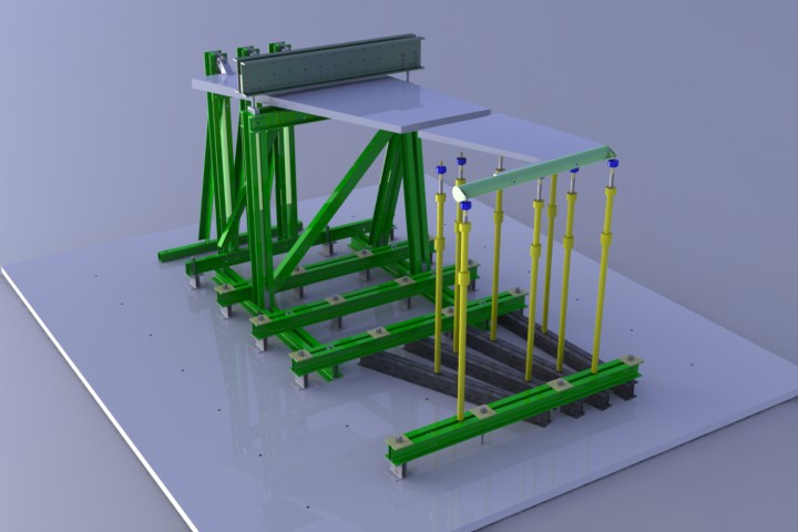
This is the dream. See the later photo for the reality. The gap between the inner and outer wings still hadn’t been filled, and the “whiffle trees” spreading the jack loads over the wing are not shown because the assembly was getting a bit big for my computer, but this is essentially the arrangement we used. The steel parts are just Australian Standard hot-rolled channel sections and there isn’t much welding in the assembly. It bolts together on connecting lugs or is clamped to hard points in the laboratory floor. Shear forces at most joints are transmitted by friction. I really like friction joints for transmitting high shear loads. They practically eliminate fatigue problems in joints and don’t need precision fits. The friction can even be enhanced by putting a sheet of open-mesh abrasive such as Norton “Screen-Bak” between the friction faces. On another test we used this method to transmit fatigue loads of over 90 tonnes via a friction joint. In that case the clamping bolts on the joint were two 42mm Class 12.9 bolts torqued to 6200 Nm (4573 foot pounds).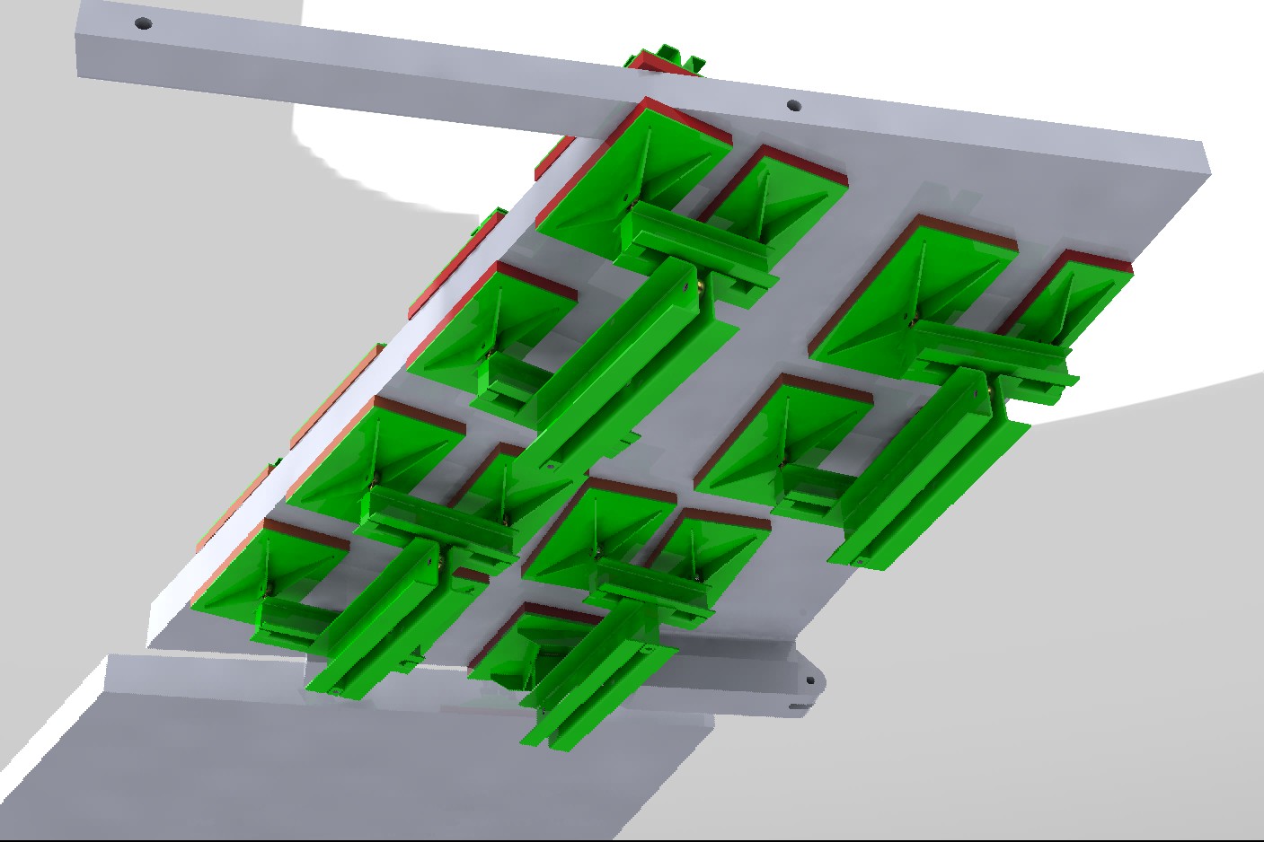
Here is a view of the wing lower surface showing the load pads and “whiffle trees”, sets of beams and bearings that distribute the load from the hydraulic jacks to the pads. “Whiffles” don’t make it into some dictionaries and I used to think it might just be a joke name, but it comes from the beam arrangements on horse-drawn carriages that enabled them to be drawn by teams of two or four horses.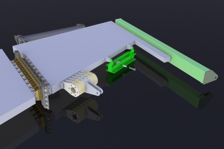
The picture above shows fittings we used to apply loads to the leading edge attachments, the dummy missile rail and also our dummy wing-fold gearbox. The inboard leading edge loading attachment looks like real overkill, and I have heard it described as ugly, but it was a tricky bit to design. We needed the very high force from the jack distributed evenly over the lugs on the front spar. From solid material, it would have been a fiddly machining job and a heat treating nightmare, so we had this part made from a series of plates and spacers. The trouble is that it’s hard to buy flat steel with a yield strength much greater than 460 MPa. At the design stage, loads had still not been finalized and it looked like we might need to put loads of up to 2.4 times DLL, which would have produced stresses of over 2000 MPa in the lugs. 460 MPa just wasn’t going to cut it. I managed to track down a billet of Nimark 350 maraging steel from a metal merchant in Melbourne. Maraging steel is very neat material which can be “age hardened” in a similar way to 2000, 6000 and 7000 series aluminium. It is usually supplied in a relatively soft machinable condition. You machine it to final size and then put it in a furnace for a time at around 500º C followed by a slow air cool. It comes out as hard as the hobs of hell, but because there is no quenching operation there is very little distortion and no final grinding operation is needed. The billet first had to be cut into thin slabs with a bandsaw, a long and expensive process in itself. Maraging steel was also used for our dummy wing-fold gearbox, but we were eventually able to acquire the genuine part so this was not needed.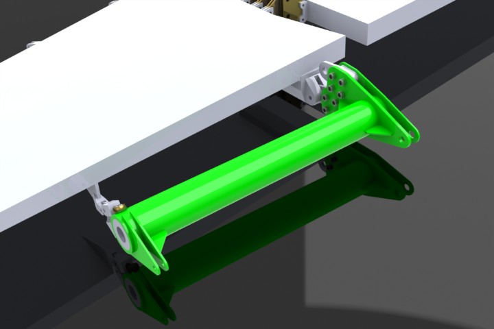
Here’s the dummy aileron. There was even a dummy actuator.
Well, 60 pages of calculations, around 150 drawings and many months later, here’s how it all came together.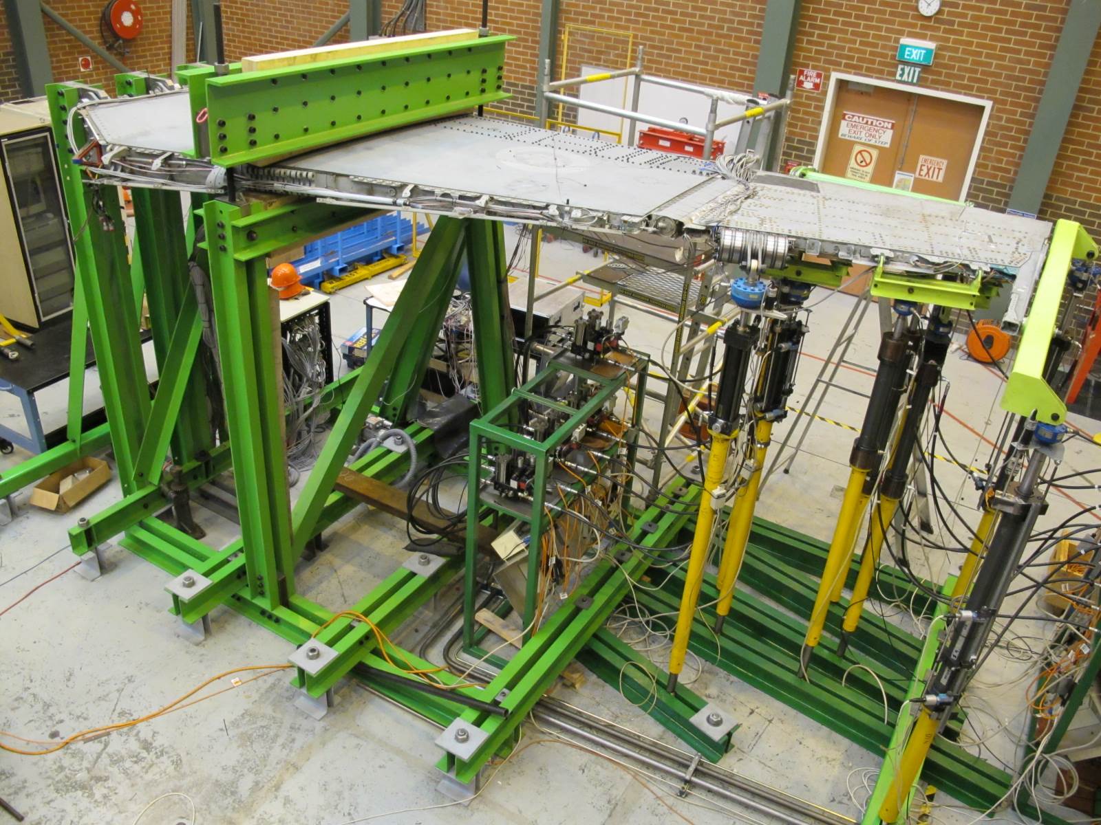
There were other glitches of course, there always are, but it all came together fairly smoothly. All the hydraulic jacks are low friction double-ended types recycled from other tests. They are driven by Moog servo-valves on locally made hydraulic valve packs and controlled by DSTO designed “Loop” controllers. The Loop controllers date from around 25 years ago, but are still as good as anything that can be bought commercially (I think better). They are simply daisy-chained together from the control computer to make a test machine with anything from 1 to more than 100 channels.
Here’s another view of the assembled rig. Remember the bit about DLL and DUL? Well the loads we used were 1.2 times DLL, so very high loads, but not high enough to break a wing that is structurally sound. That wing looks absolutely awesome being bent by a big load, but we haven’t broken it – yet.
Thanks to DSTG, the Defence Science and Technology Group for permission to use the illustrations and photographs.
For more official information on this test, visit:
DSTO Presentation on FINAL and HOWSAT etc
Peter Anson