FINAL test – Flaw IdeNtification through Applied Load
You can see they were really struggling in the Acronym Department when they named this one. It’s not a patch on FLACID, for FLAw and Crack IDentification, or CRACKPOT IDEA for CRACK POTential IDEntification and Analysis, but sometimes good ideas just aren’t recognized.
For a more official explanation of the test, click here.
A critical part limiting the fatigue life of F18s is the “centre barrel”, the set of three fuselage frames to which the wings attach. There is a program to change over the centre barrels but not surprisingly, it’s hugely expensive. The idea behind the FINAL program was to apply fatigue loading to old centre barrels, ones that were “life-expired”, to grow any existing cracks to failure. By microscopically examining the crack face, you can back-track to a time when it should have been detectable and get a better idea of the safe life of the aircraft. My job was rig design and manufacture, but I also helped with assembling and running the test for a while.
Here’s the idea:
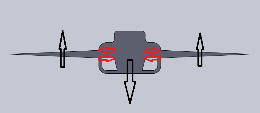
The weight of the aircraft is carried by the aerodynamic forces on the wings. At the wing root, the bending moment on the wing is reacted by a couple of much higher forces (the red arrows). In truth, there is also an equal and opposite shear force at the wing root (half the big arrow) but to simplify things we’ll sort of ignore that bit (despite their sizes in the drawing, the red arrows represent much bigger forces than the black arrows). Not applying that shear load means we don’t have to hold the fuselage down which makes the rig very simple, just three sets of beams on each side to apply a bending moment, and for mounting, it can simply sit on its side on one set of beams. To allow for bending of the beams we actually had it sitting on a couple of strips of wood. I seem to remember this originally being described as a “quick and dirty” test, but that was 12 years ago and it’s ongoing.
The Rig
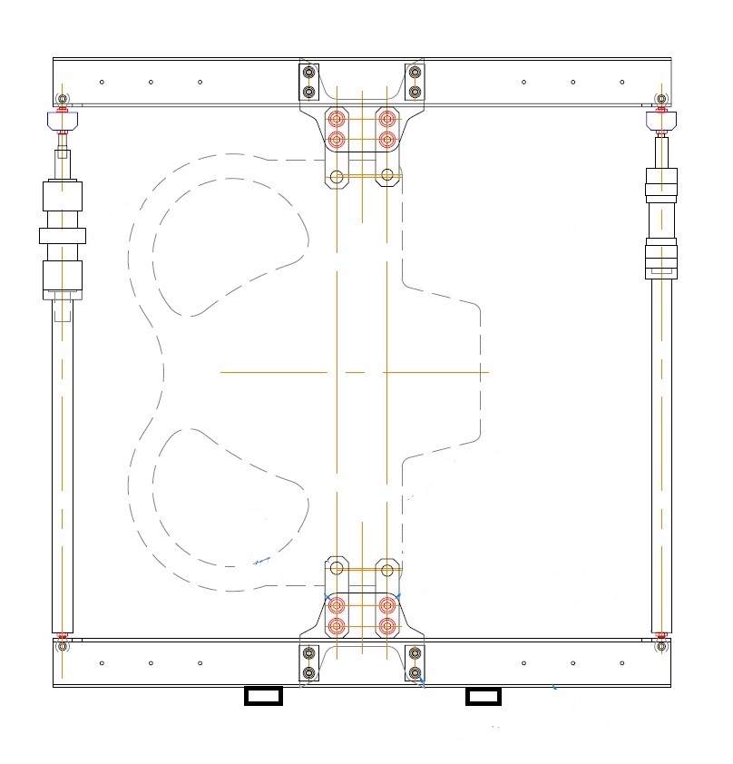
Multiply that by 3 and that’s the test rig. The jacks work in tandem, one pushing and one pulling. The different jacks shown in the drawing are the two types we scrounged from other tests. They push and pull the ends of a beam that is attached to the one of three fuselage frames by a two pairs of lugs and a steel plate.
Here’s the attachment to the centre barrel – just a big steel plate between two channels and some lugs to the fuselage frames.
The smaller jacks have a capacity of 80 kN (18,000 pounds) but with that nice big lever, the maximum forces are:
where beams attach to the plate by 30 mm bolts – 451 kN (101,000 pounds)
where lugs attach to the plate and centre barrel – 943 kN (212,000 pounds).
If you look at industrial equipment that is built to support 100 tons, it is pretty massive, but in this case it also had to fit in limited space. The lugs shown in the drawing had to be extensively hand finished to fit in with parts on the aircraft. So here’s the requirement:
- Apply huge cyclic loading
- Fit into the same space as the very high strength aircraft materials.
- Last longer than the very high strength aircraft materials.
- Be made from available industrial materials.
On the plus side, we could make some parts bigger and heavier because it didn’t have to fly, and nobody was going to die if things broke.*
* A couple of lugs did eventually fail after the equivalent of many aircraft lives, and one bit came out with enough energy to dent a safety screen.
Beams are just back-to-back Australian Standard 250PFC (250mm wide parallel flange channel). Making an effective “I” beam out of two “C” beams is useful in this sort of application because loads can be fed in centrally without the need for any welding.
The centre plate is just C350 plate – mild steel if you like. The odd cut-out you might notice on the bottom of the plate is just for economy – the front cut-out of one plate becomes the back of the next plate.
Lugs are from Theissen “Thyroplast 2738”, a tool steel intended for making injection moulds, but in our case used because it was available in suitable sizes and could be heat treated.
The bolted joints here are friction joints with all the bolts in clearance holes. The 42 mm Class 12.9 bolts were torqued to 6270 Nm (4630 foot pounds) using a hydraulic wrench. Even the “little” 30 mm bolts had to be torqued to 2250 Nm (1660 foot pounds).
The pins that attach the lugs to the real bit of aeroplane were also a legacy of a previous test. They were tubular split sleeves with an internal tapered mandrel which pulled into the tube to make a perfect fitting pin. The sleeves were machined, heat treated, shot-peened and finally ground to size. They were expensive to make so I tried a couple of different re-designs, but none of my efforts were as good as the originals.
We had one of the 42mm bolts fail when we tried to re-use them so always replaced them after that. I can tell you that a 42mm bolt breaking while you are holding the spanner that’s tightening it makes a very loud bang.
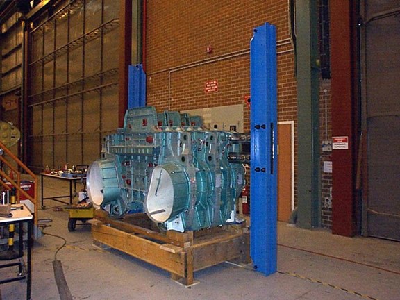
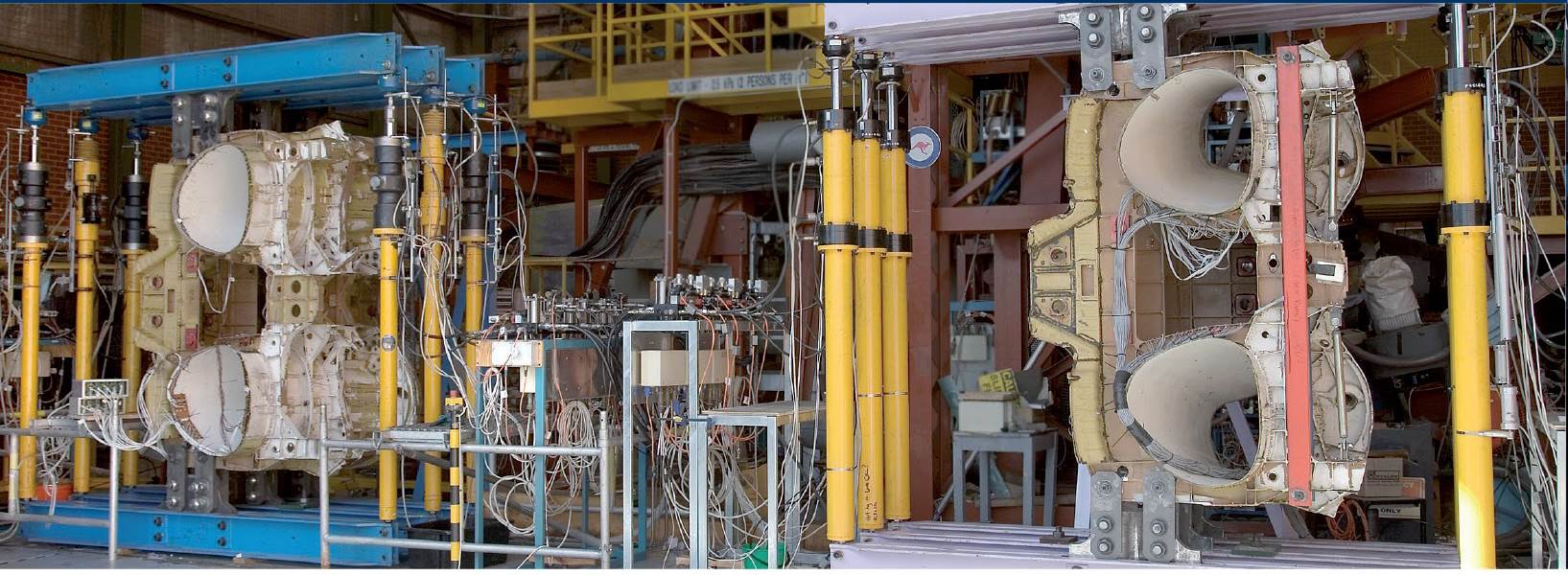
The complete rig, now with a sibling. The rig on the right is a heavier duty model that was originally built for a related test for the US Navy. When I picked the colour, I wanted a light colour that would show up any cracks, but something other than blue. Why not mauve? So I checked a colour chart and found “Lilac Lust”. That’s the sort of name you want to see on an engineering drawing. It became universally known as the “Pink Rig”, and I can recall some visiting USAF officers asking about it. When they found that the pink rig was being used for a USN test their comments proved that inter-service rivalry was alive and well.
Things go Worng
Friction joints
Initially they were not quite up to the task. The first time we took the rig to a really big load there was a series of very loud bangs as things settled into place. Fortunately the -g loads were smaller than the +g loads so once everything had settled into place it worked OK. On later assemblies we used Screenbak, an open-weave abrasive sheet in the joints and the problem was solved.
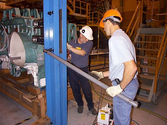
Wing pin fretting and “welding”
I think that on service aircraft the wing-to-fuselage pins are removed and checked/relubricated every couple of hundred hours but we were doing the equivalent flight time in around a week. It just wasn’t practical to disassemble the thing so often. When we eventually disassembled the first test, some of the pins had welded themselves into the lugs.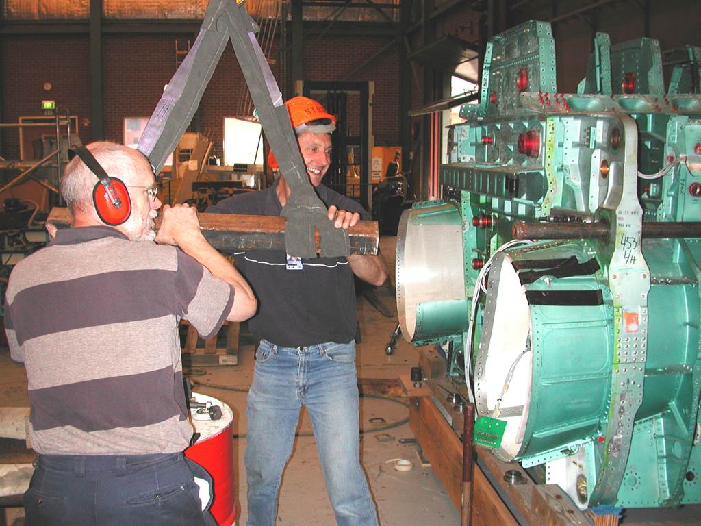
Here we are using a battering ram made out of the biggest lump of steel we could find suspended from the crane to hammer out the last pin. The picture is a little bit staged for the benefit of the task manager, but we really did use this method after giving up on the sledge hammer, which can be seen leaning against the centre barrel. We used a baked-on moly-disulphide coating on the pins after this and the problem was largely solved. In future tests the lugs were also gas-nitrided to make the surface harder.
Fatigue cracking around the jack boss
At the ends of the beams were welded in bosses where the rod-ends on the jacks connect to the beam. At some stage they developed “eyebrows”, fatigue cracks around the heat-affected zone. In theory, the stress was low, but practice said otherwise. The solution was pretty simple. We turned the beams over, bored holes on the opposite side and pressed in interference-fit bushes.
Fatigue cracking of lugs
There wasn’t a lot I could do about this one. We were clean out of unobtanium and I didn’t want to make the lugs thicker because I was worried about increasing the already high bending stress on the pins. It was a reasonably rare occurrence. More recently, an even heavier rig has been built which does have thicker lugs, so I might yet be proven wrong on that one.
Results
If you follow that link near the start of the page you will find that one of the more startling results is that for an initial outlay of around a million dollars, the test saved hundreds of millions of dollars.
Personally, I learned a lot. Tests like this are fairly straightforward design jobs because you at least have a very good idea of the loads, but there is always the chance of a surprise, like getting to the end of a test and finding that they are intending to bump the maximum load up by 20% for a residual strength test. Oh, and structures as strong as F18 fuselage frames make very loud bangs when they break.