Sturart Trist’s Outback AdventureI better state here and now that I’m not an expert on metal fatigue, but in the course of my work a bit of knowledge rubbed off and I got pretty good at finding fatigue cracks, partly through perseverance and partly through knowing likely places to look.
You probably know that “metal fatigue” refers to the failure of a metal component or structure due to repeated loadings when the individual loads are somewhat less than a single load which would be required to break the part. A simple example is breaking a piece of wire by repeatedly bending it back and forth until it eventually breaks. One of the things you will have been aware of as you bend that bit of wire back and forth is that you are deforming the metal plastically, that is the metal is being permanently deformed or “strained”. Repeated plastic strain, usually in microscopically small regions, is what initiates and drives fatigue cracks. The repeated loads cause the crack to grow until there is not enough material left to support the load and the part breaks, apparently without warning.
First, a couple of definitions:
Stress: Stress is defined as force per unit area. Mathematically, that’s:
σ = F/A hence pounds per square inch or PSI
Engineers often use thousands of pounds per square inch or KSI. The metric equivalent is Newtons per square meter or Pascals. The Pascal is such a tiny unit that in structural engineering it is more usual to use Megapascals, which happen to be the same as Newtons per square millimeter.
Strain: strain is defined as the change in length per unit of length, Mathematically that’s:
Ɛ = Δ length/length Since strain is just a ratio, there is no unit name
Elastic strain: Metals are crystalline solids. Think of them as grids of molecules connected by springy molecular bonds. If a load is applied to a metal part, the amount that it deforms is dependent on the strength and arrangement of those molecular bonds. When the load is removed the bonds snap back and the part goes back to its original shape.
Plastic strain: Those molecular bonds are very strong and if metals were perfect crystalline solids they would be much stronger than they are, but all metals have flaws called dislocations which are in effect partially missing layers of molecules. At the edge of the missing layer is a row of molecules that are not completely bonded. If the force on metal is high enough the dislocation can move from layer to layer causing permanent or “plastic” deformation. See dislocation movement for a demonstration of how the dislocations move. While plastic deformation makes metals much weaker than they should be in theory, it’s not all bad news. Much of our ability to form things in metal relies on our ability to bend, roll and stretch metal into different shapes
Plastic strain and initiation of fatigue cracks
Plastic strain is important because under repeated plastic strain those dislocations form microscopic extrusions and intrusions at grain boundaries. The intrusions are effectively very sharp surface defects which initiate fatigue cracks. The obvious solution is to design parts so that they are not plastically strained, but in a practical light-weight structure that is difficult to do. Any discontinuity in a part acts as a local stress raiser. For example, the stress immediately adjacent to a hole is at least 3 times higher than the stress in the surrounding material. At sharp corners it is common for the local stress to be 5 times higher than the surrounding material. Sonex and other kit suppliers instruct builders to avoid making any sharp notches and corners, but it’s pretty hard to avoid holes. There are probably about 15 to 20,000 of them in a small metal aircraft.
Here’s a way to visualize the stress around a hole. Imagine the lines are lines of force through the material. The closer the lines, the higher the stress.
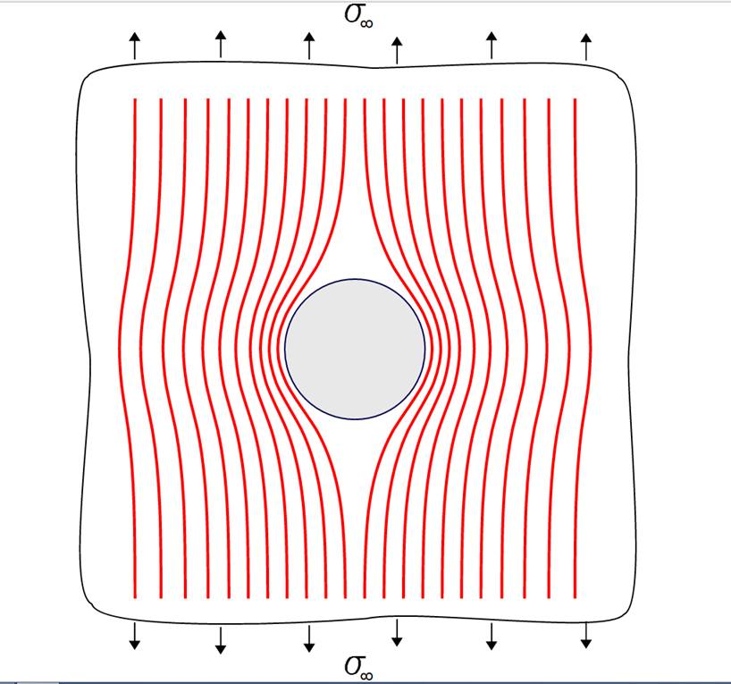
If we draw a little graph of the stress on the surface of the material, here’s what it would look like.
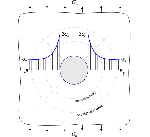
You’ll notice that the stress adjacent to the hole is 3 times the stress away from the hole. This can be shown by careful finite element analysis (FEA) but it has also been proven by extensive testing. Test specimens with a drilled hole have a similar fatigue life to an undrilled part carrying 3 times the stress.
Tension and Compression Stresses
Repeated tension stress is what drives fatigue cracks, you are trying to pull the material apart after all, but compression stress can be important too. While repeated compression stress is not going to cause a fatigue crack to grow, the occasional compression stress can have the effect of sharpening a crack, thus speeding up crack growth. By contrast, the occasional large tension stress in a sequence of much smaller tension stresses can temporarily slow down crack growth by “blunting” the fatigue crack.
Likely locations of fatigue cracks
Fatigue is not generally a problem in home-built aircraft, largely because most of us don’t do many flying hours and also because most of us don’t do many high-load maneuvers. Never-the-less I have seen several instances of fatigue failures in Sonex aircraft, mostly in welded steel parts including tail-wheel castors, tail-spring brackets and engine mounts. Sonex alterations to the design of the rudder pedals hint that there were failures in the earlier design.
In general, fatigue cracks are most likely to occur in parts of a structure that are predominantly loaded in tension: the lower surface of the wing, the upper surface of the tailplane and the upper longerons, but most cracks will start at a stress raiser, a hole or discontinuity of some sort. Cracks will grow at right angles to the direction of stress, for example, a crack in a wing skin will generally grow forward or back. A crack in a longeron will grow across the longeron.
Wing main spar
The diagram below represents the main spar of one wing showing the forces acting on it. All the little arrows represent the aerodynamic forces pushing up on the wing. They are reacted by the two large arrows at the wing attachment points. The aerodynamic forces are tending to bend the wing upwards, compressing the top of the spar and stretching the bottom, so the lower face of the spar is the bit we are most interested in. The graph below the spar is a bending moment diagram scaled to match the spar. The bending moment is effectively the combination of force times distance that is trying to break the spar, and you can see that the maximum bending moment is at the wing attachment point. The designers of the Sonex have taken this into account of course and that part of the spar is the strongest.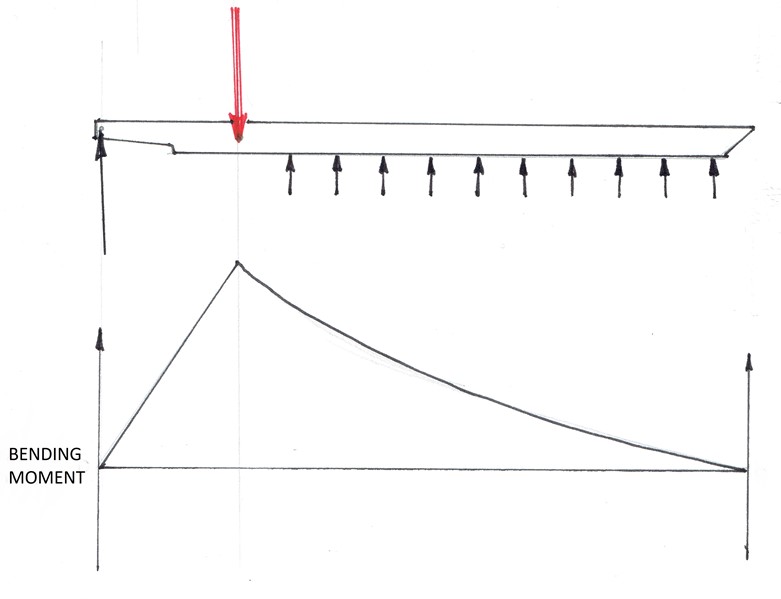
You can see from the graph, that halfway between the reaction loads, and also halfway across the fuselage, the bending moment is half maximum, but that is also the part of the spar that is heavily cut away so that the spars can cross over. Again, Sonex designers have taken this into account by heavily reinforcing with extra pieces of angle riveted to the spar web, but still, it is a stress raiser. This part of the wing is not normally accessible but if you have to remove the wings at any time I think it would be worth a visual inspection. Note that I am not saying the spar is weak or that you should expect fatigue cracks here, just that the most likely place for a fatigue crack would be from that cutout on the lower edge of the spar.
Fuselage top longeron in the cabin
The diagram below represents the main loads on the fuselage; engine, fuel , occupants and the balancing load supplied by the tailplane/elevator. I haven’t bothered to show it but there is also the weight of the airframe itself. All these forces are balanced by the aerodynamic loading of the wing. All the forces are tending to bend the fuselage downwards, so that the bottom of the fuselage is being compressed and the top is being stretched.
A graph of the bending moment , scaled to match the fuselage would look something like the above. Maximum bending moment is in the region of the cockpit and the highest tension loads are experienced by the top longerons. I have never heard of any Sonexes experiencing fatigue cracks in the top longerons, but that doesn’t mean it won’t happen, and it’s an easy region to inspect. I would concentrate on all those open holes that are there for canopy latches and windscreen bows, but especially at the splice joints where the tail-cone attaches to the forward fuselage.
Known fatigue crack regions on Sonex
These are all welded steel parts which if made by Sonex are black powder coated. Sonex say that fatigue cracks will show on the powder coated parts as a white line, but this is not my experience, at least with painted parts. On painted parts cracks will sometimes appear as a fine black line which will obviously not show up on a black surface, but paint, especially thick paint, can hide quite long cracks. If you are painting steel parts I would recommend a light colour.
Steel tail-wheel castor
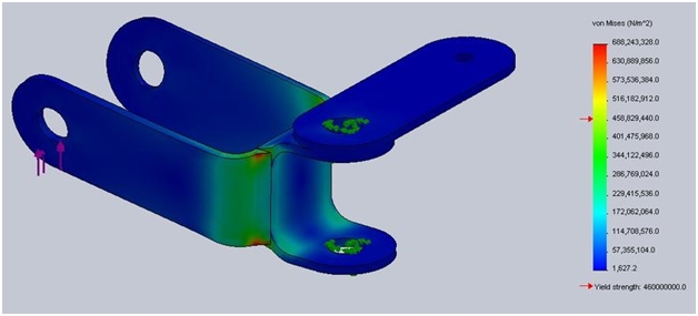 In the FEA model shown here, the load applied to the axle holes is 1000 Newtons (225 pounds) which would probably be a pretty hard bang on the ground, but the maximum stress is way above the elastic strain limit. Cracks are likely to grow from the zones shown in red in the diagram. Making the arms longer to fit a 6″ tail-wheel will exacerbate the problem. Try to keep those landings smooth. The good news is that a failure of the castor will probably be inconvenient rather than dangerous.
Tail spring bracket
I don’t have a pretty picture of this part, and it’s tricky to model (for me anyway) being effectively a composite part of the titanium tail spring and the steel tail spring bracket. Titanium has nearly twice the yield strength of 4130N steel but only a bit over half the stiffness. When materials of different stiffness share a load, the stiffer one carries most of the load (think of the fibres in fibre-composite materials), so that where the titanium tail spring is inserted into the bracket, the weaker steel tube is doing most of the work. The end result is that the brackets can fail by either the tube cracking or the rear plate cracking, and I have seen a couple of instances of this. The good news again is that failure of the bracket is probably not dangerous.
Engine mount
The diagram below is a somewhat simplified model of the Sonex lower engine mount loaded by just half the engine weight – the 1 G case.
The danger area is that little red zone at the intersection of the tubes. An acceleration of just 3.7g will cause stress to exceed yield point in that zone. There are a couple of other factors here: this is a weld heat-affected zone so yield strength could be lower; the above model is just a basic Solidworks analysis so the finite element grid is not particularly fine – stress at this point could be even higher. Now you might think that you will rarely see 3.7g in your Sonex, and that could be right, but I have recorded up to 6.9gs in summer thermals in mine. At some point Sonex changed the specification for wall thickness of that tube from 0.035″ to 0.049″ (the model above uses 0.049″). The following link is to a trip report where Stuart Trist experienced exactly this failure. His is a fairly early kit so the engine mount is probably the earlier 0.035″ type but his engine was the very light Jabiru 2200. https://www.sonexaus.org.au/wp-content/uploads/2018/07/Trist_outback0915091.pdf
I would urge people to check this region very carefully every service.
What do fatigue cracks look like?
The answer is; it depends, on material type and also thickness. Ideally , you want to find fatigue cracks when they are small, but of course that is when they are hardest to see.
Here’s an example of a fatigue crack in thick material. It’s a bit unusual in that this link is predominantly loaded in compression, but the bearing load is tending to split the rod so that the crack is growing along the centre of the rod, something I have not seen before. You can see it right? Try clicking on the image to enlarge it and follow the red arrow. In this case, the test aircraft had done the equivalent of around 28,000 hours, way beyond the life if this type of aircraft.
Above is a close-up of a similar crack taken with a small USB microscope.
Here is an example of a crack in thinner material, in this case the al. is between 2 and 3 mm thick and the crack has grown each side of the rivet to a total length of about 25mm. The crack is long enough so that as the crack opens and closes, a black fretting material is produced which in this case gave away the location which was well out of sight and photographed with a camera poked into an inspection hole. After finding this crack we checked the same location on the other wing and hey presto, a mirror image.
Cracks in thin material are not always easy to see. This one is only a few millimetres long, but you know the saying; “from little things, big things grow”. The brownish stuff is a composite patch over a previous crack in this region and the misshapen hole is from the rivet wiggling in the hole.
Useful tools for inspection
Mark One Eyeball – Surprisingly just looking at things will often find cracks
Inspection mirror – These are pretty cheap and useful for aiding the M1 eyeball.
Magnifying glass – My eyesight is not great and I find these pretty handy
Compact digital camera – Most modern compact cameras are capable of taking very close-up images in “macro” mode and the image can then be enlarged to show up flaws. I have a Nikon Coolpix S7000 that can focus down to 20mm. Most other compact cameras will focus down to less than 50mm which is easily good enough.
USB microscope – You can buy cheap ones on eBay for around $25. The best type I have used is a “Dinolite” which looks much like the $25 job but seems to have better optics. Dinolites range from around $100 to $250 but we found the cheaper model Dinolites more useful.
Dye Penetrant Kits – you are unlikely to need these. I used a penetrating dye to check a cylinder on my engine that had a suspicious line around the cylinder base. Since the possible crack was in fairly thick steel I couldn’t determine whether it was a crack even with a microscope. The dye makes a hell of a mess but proved that the “crack” was nothing but a line on the surface from machining.
What to do if you find a crack
For a start, congratulations, you dodged a bullet. It’s not the end of your world, well not now anyway. The answer as always is, it depends, but usually you will need to either repair or replace the damaged part. At the very least you should monitor the crack. Repairs could be as simple as stop-drilling or blending out a small crack up to fitting a patch which can take the load from the cracked part, but most of us don’t have the expertise to design repair patches, and even experts muck that up at times. Cracks in secondary structure can sometimes be tolerated. Cracks in primary structure, wing spars, fuselage longerons and engine mounts cannot be ignored.